To cut the wooden board I prepared earlier, I used the school’s 3D workshop. I also carried out 3D printing at the same time to reprint the binder that had not fit properly due to incorrect measurements.
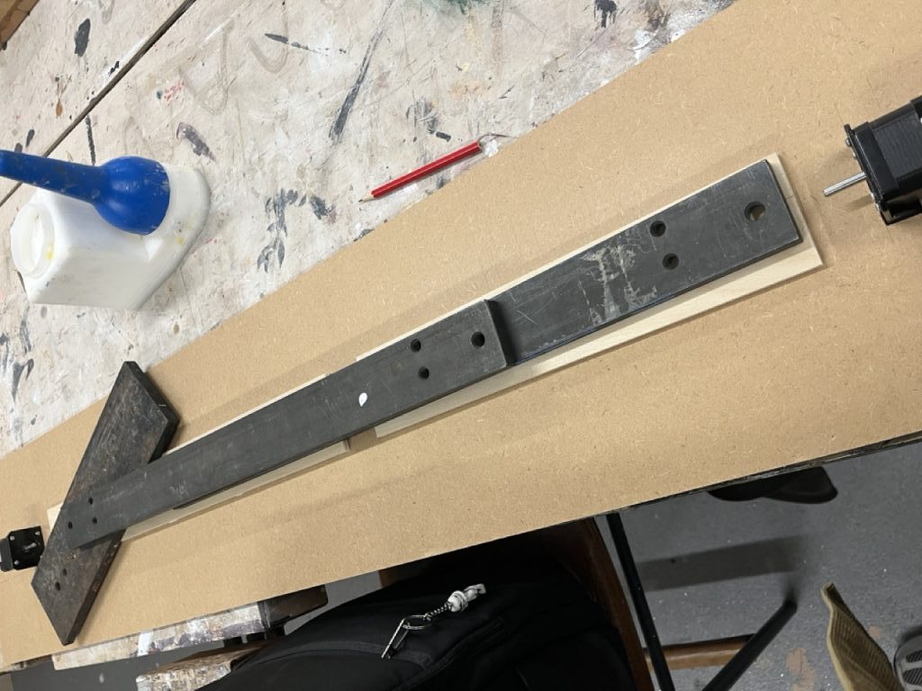
The first task was to create a small rectangular hole where the motor could be fixed. I cut the hole to a size that would allow only the front part of the motor mount to protrude upward, and fortunately, the opening fit well. However, the hole on one side was slightly too large, causing the motor to wobble a little. I will need to check later whether this will have a significant effect once the system is running. To reduce the height difference between the motor and the rail, I added an additional wooden plate of matching thickness and glued it in place. After the wooden plate was secured, I aligned the position of the rail brackets and drilled the necessary holes. Then I drilled another slightly larger hole at the back of the motor to route the wiring through. After that, I glued legs to both ends and the center of the board to create sufficient space underneath. Any smaller holes needed later will be drilled at home.
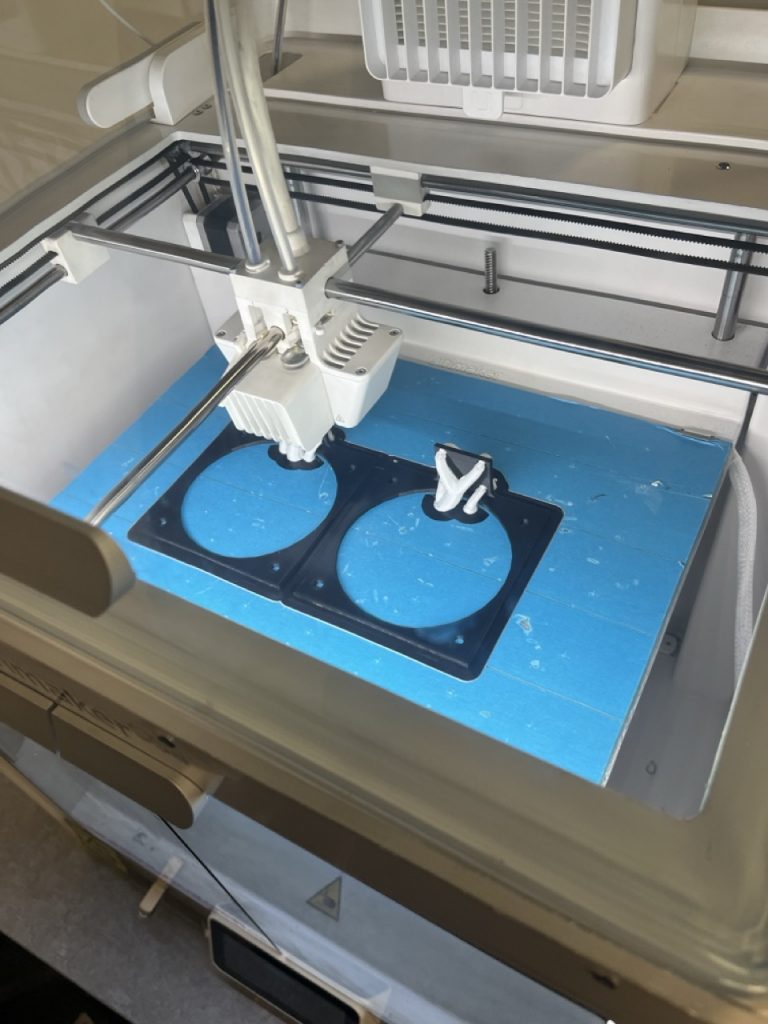
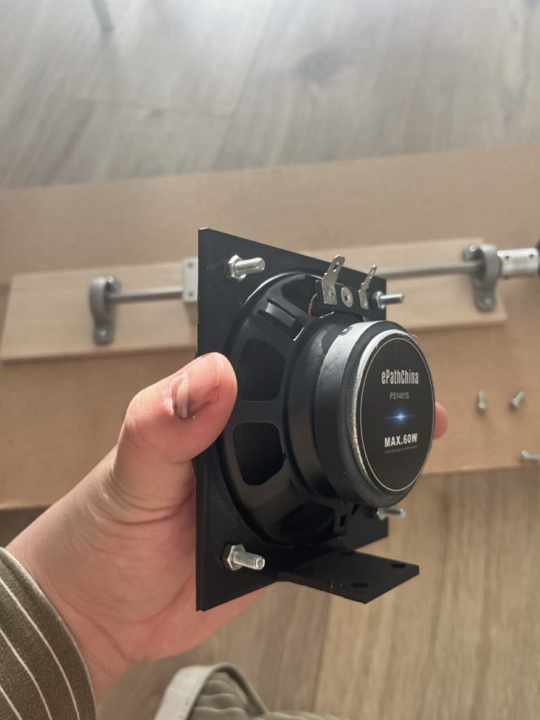
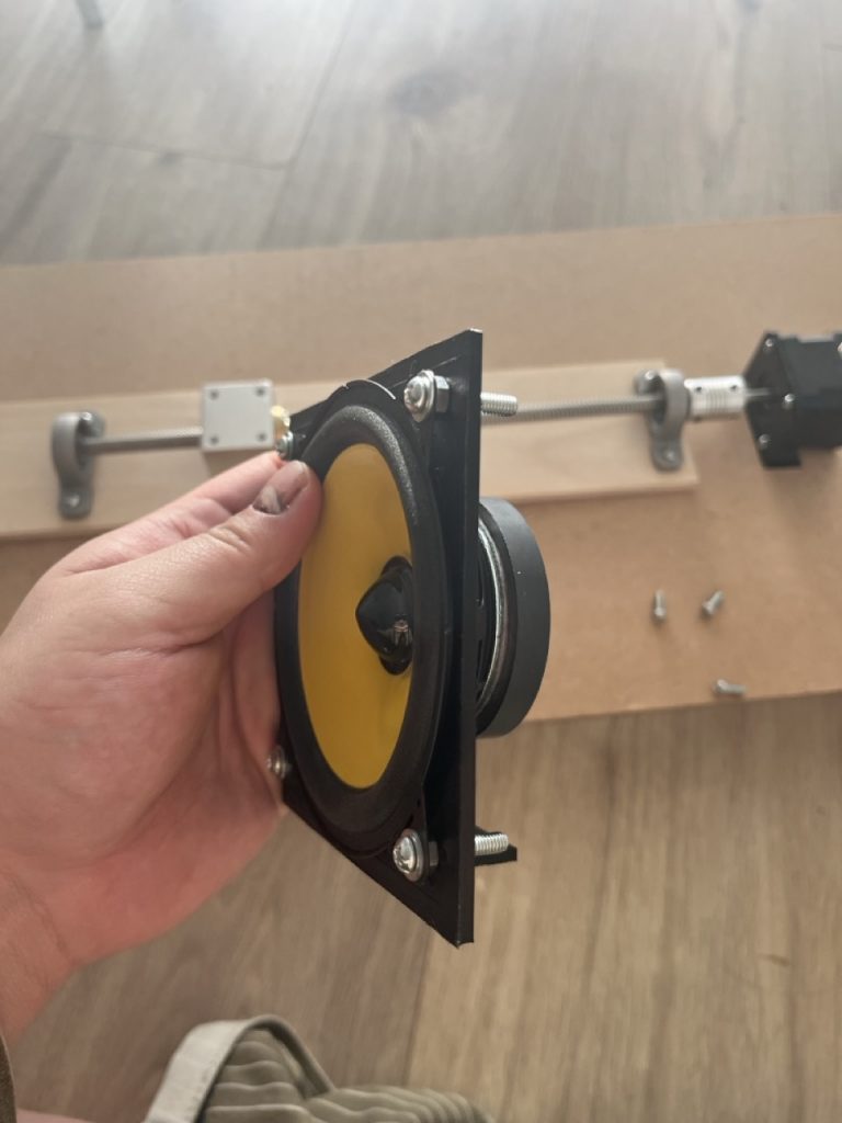
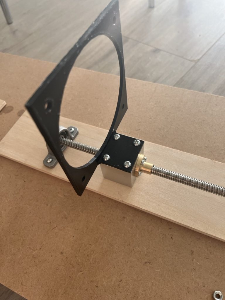
For the 3D printing, I re-measured all the dimensions carefully and examined which parts had not fit previously and why the errors had occurred. Keeping those issues in mind, I redid the 3D modeling and printed a new binder. This time, the printed binder matched the intended dimensions and fit well with both the speaker and the carrier block.
Next, I plan to assemble the motor, rail, speaker, and limit switches together on the rail and then connect all the wiring to run a full operational test.