After completing the modeling of the joint component that connects the carrier box and the speaker, I produced it using 3D printing. Unfortunately, the printed part did not fit properly with either the speaker or the carrier box—likely due to inaccuracies in the modeling or errors in measurement.
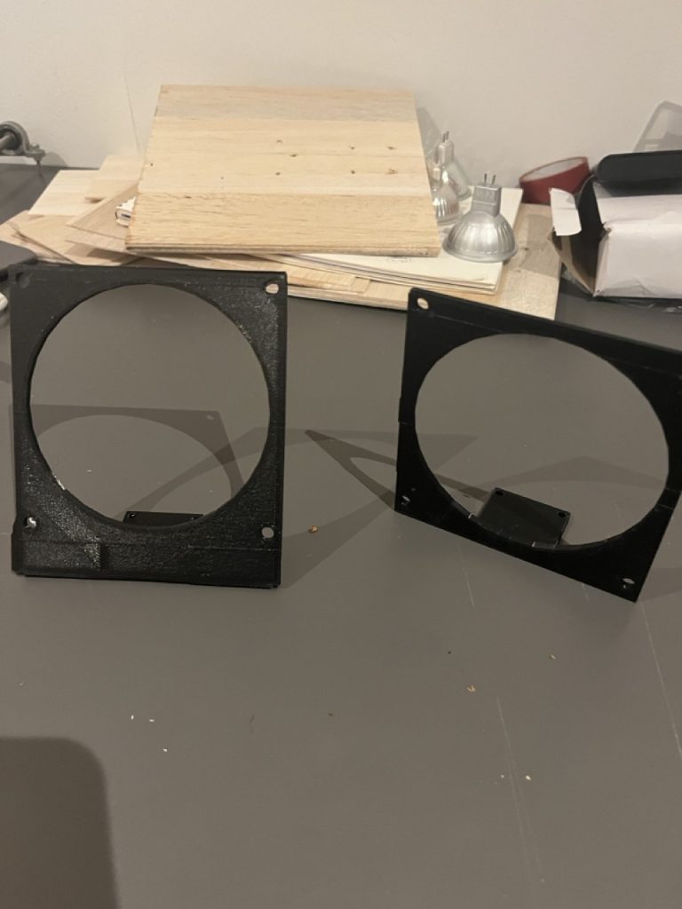
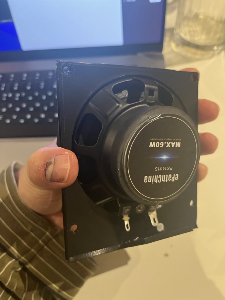
Looking more closely, the issue with the speaker turned out to be a measurement error. When measuring, I based the dimensions on the bumper at the front side of the speaker, but the protruding section on the back is slightly larger, which prevented the speaker from fitting into the circular opening. For the next iteration, the diameter of this circle needs to be increased. In addition, the location of the holes does not align correctly. Whether due to calculation errors or inaccurate reference points, the holes in the connector part were positioned too far apart. For the next measurement, I should be able to determine the correct hole positions more easily by comparing the faulty model with the speaker.
As for the mismatch with the carrier box, there were two issues. First, there was an error in the measured width of the carrier box. I initially measured it as 33 mm, but upon re-measurement it turned out to be 34 mm, so this must be corrected. Second, the opening where the bolt inserts is too small. The bolt does not fasten directly to the connector piece; instead, the connector is held in place between the bolts fixed to the carrier box. Therefore, the hole should be modeled slightly larger next time to allow enough clearance.
I also completed testing with the limit switches. Previously, the rail system simply moved the carrier box back and forth over a fixed distance, but this would likely cause problems during an exhibition or in real installation conditions. I therefore changed the mechanism so that the carrier box reverses direction whenever it presses the limit switch installed at either end of the rail. I tested this using the limit switches, and it worked successfully. The switches were programmed using an INPUT_PULLUP configuration, allowing the motor direction to reverse when triggered. However, due to insufficient debouncing, the motor experiences slight strain when the switch vibrates or chatters upon contact. In the next experiment, I plan to increase the debounce delay in the code.
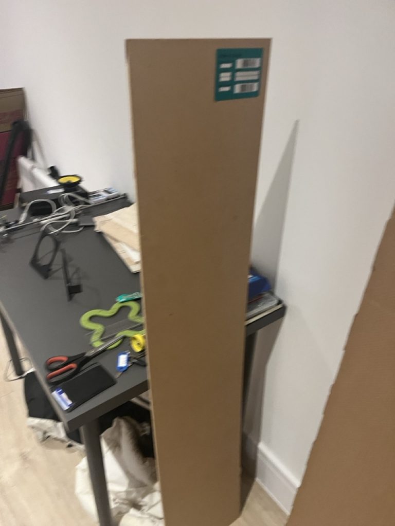
This week, I purchased a long wooden board from B&Q. I will now begin arranging the motor, rail, and other components on it, taking height differences and spacing into consideration. I will also mount the limit switches and test whether the carrier box can reliably trigger them during movement.