First, the implementation of the screw linear system, including its combination and movement, has been completed. However, a height difference occurred between the motor and the screw linear when they were combined. To ensure the carrier box moves without twisting, it needs to be securely fixed. For now, we have adjusted this height difference using bolts and nuts. In a previous post, I mentioned that we should consider whether the movement should be uniform or accelerated, but after several experiments, what is currently important is not the speed, but rather moving the carrier box to its end limits and how to attach the speaker to the carrier box.
To address this height difference, we need to consider a plate to support the carrier box and a method to reduce the gap between the motor and the screw. Initially, I thought about matching the height by raising only the part of the plate (made of wood or steel) where the carrier box passes, and adjusting the height difference for the screw holder and motor using bolts and nuts. However, I realized that if the motor, screw, and other components were all attached to the top of the plate, it would look messy and make wire management difficult. So, I started thinking about hiding all components except the speaker behind the plate. This would make adjusting the height difference between the motor and screw much easier. The only problem then is what will support the carrier box itself.
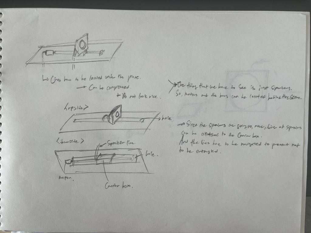
There are several methods for this. The first is to attach a wide plate to the carrier box itself and support it from the sides of this plate. The second is to attach guide rails on both sides and connect them to the box for stability. This method is much more stable but requires attaching two more rails of the same length on both sides, so space considerations need to be studied. The third method is for the connection part between the speaker and the carrier box to also serve as a support. However, this connection part will be made with 3D printing, and it’s uncertain whether it can withstand the required strength. For now, since we need to create the connection part between the speaker and the carrier box first, we will make various versions of this connection part, including versions that can also support the carrier box.
Also, in a previous post, I wrote that research was needed on how many motor rotations it takes for the carrier box to reach the end, but I’ve realized this method is not good. This is because the motor is driven by an Arduino, and if the Arduino’s power is turned off and on again, it will execute the code from the beginning. If the carrier box is not in its initial position at that time, excessive over-rotation could cause problems. Therefore, it will be necessary to design it with switches or sensors on both sides so that the motor can change its direction of rotation when the carrier box reaches the end. Let’s research this in more detail next time.
So, my next three tasks are: first, connecting the speaker and the carrier box; second, researching an appropriate method for supporting the carrier box (this research will be conducted after studying the support structure itself, as it also requires a stand); and finally, changing the motor’s direction of rotation when the carrier box reaches the end.